Introduction
I2C stands for the Inter-Integrated Circuit protocol. I2C was developed in 1982 by Philips Semiconductor as a low-speed communication protocol for connecting controller devices such as microcontrollers and processors with target devices such as data converters and other peripheral devices(like temperature sensor, EEPROM).
Need of I2C
In numerous instances, a microcontroller or microprocessor needs to communicate with its I/O devices. Consider a scenario where an EEPROM, possessing a small memory storage capacity, is interfaced with a microcontroller within an object detection device. This device is tasked with counting the number of balls of various colours—blue, white, red, and black—as they pass through. A colour sensor identifies the colour of each ball, and the running code calculates the ball count. However, this count data is susceptible to loss in the event of a power outage.
To ensure the preservation of count data and facilitate the resumption of counting after a power cycle, the microcontroller employs an EEPROM for storage. The EEPROM consists of multiple memory locations and for instance, specific addresses such as 0x00 are allocated for blue ball count, 0x10 for black ball count, 0x20 for white ball count, and so forth. To write the count data based on the ball colour, the microcontroller selects the appropriate address and performs a write operation.
Similarly, for reading the count data, the microcontroller selects the relevant address and executes a read operation. While data reading from peripheral devices may be minimal, establishing communication between the CPU and I/O devices involves implementing various protocols. Among these, the I2C (Inter-Integrated Circuit) protocol proves to be a suitable choice. This protocol facilitates the seamless exchange of data between the microcontroller and the EEPROM, ensuring efficient storage and retrieval of ball count information.
Let’s delve into how we can fulfil the need to store and retrieve data from an EEPROM using the I2C protocol.
What is I2C
I2C (Inter-Integrated Circuit) is a bidirectional, half-duplex serial communication protocol. This means that data transmission can occur in both directions, but only one direction is allowed at any given moment.
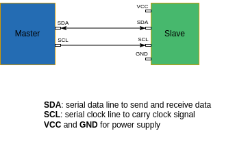
I2C uses a master-slave architecture, where a master device(controller or processor) initiates communication with one or more slave devices(i/o device) on the same bus. The direction of communication is controlled by the master device, which initiates and manages the communication. It utilises two lines for communication: a data line (SDA – Serial Data) and a clock line (SCL – Serial Clock). Lets see how this protocol works with one master and one slave, later we will check on multi master multi slave.
The connection between one master and one slave is given below:

How data is exchanged?
In I2C communication, data is conveyed using binary 1s and 0s. The state of the Serial Data (SDA) line determines the binary value: a high line represents binary 1, while a low line represents binary 0. The sender switches the SDA line in a serial order to communicate a message. This involves a sequence of transitions on the SDA line, synchronised with the Serial Clock (SCL) signal. During data transmission, changes in the state of the SDA line only occur when the clock signal is low. The clock signal, managed by the master, governs when data bits are either transmitted or received. Each clock cycle corresponds to the transfer of a data bit.
When the clock signal rises (transitioning from low to high), it signifies a check on the SDA line. If SDA is high during this check, it corresponds to binary 1; if low, it corresponds to binary 0. This process repeats with every clock pulse.
By monitoring the alterations in the SDA line’s state and aligning them with clock pulses, the receiving end decodes the binary data being transmitted.
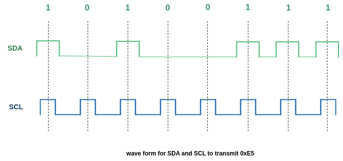
Let’s take a 8 bit data transfer as an example:
Data = 0xE5
The binary representation of 0xE5 is 1110101, In I2C data bits are transferred from MSB to LSB. The clock signal and its corresponding SDA line is shown in the diagram below.

How I2C communication starts and stops?
The initiation and termination of I2C communication are determined by changes in the state of the SDA and SCL lines. Specifically, if the SDA state transitions while the clock (SCL) is high, it indicates the start or stop of an I2C communication sequence.
When the SDA state is pulled low while the clock is high, it signifies the beginning of an I2C communication, indicating a start condition. Data transmission commences from this point. Conversely, when the SDA state is released or set high while the clock is high, it denotes the end of I2C communication, representing a stop condition.
Message Format
I2C communications involve the exchange of data through a structured message format:

Start condition
The initiation of an I2C communication by the Master.
Address Frame
The address of the Slave that the Master wants to access. The master broadcasts the address of the desired slave to all connected slaves. Subsequently, each slave compares the received address from the master with its own. In the event of a match, the slave transmits a low voltage ACK bit back to the master.
Read/Write bit
A bit indicating whether the Master intends to send data (0) or request data (1).
ACK bit
An acknowledgment bit from the Slave corresponding to the address.
Data Frames
For data transmission from the Master, the SDA line is controlled by the Master. If the Master is requesting data, the SDA line is controlled by the Slave to allow the Master to read the data.
ACK bit
An acknowledgment by the receiver, indicating that the data frame has been received.
Stop condition
Initiated by the Master to conclude the I2C communication.
I2C communication with EEPROM
Lets see how can we achieve writing and reading from EEPROM to fulfill the object detection device operation which is mentioned earlier.
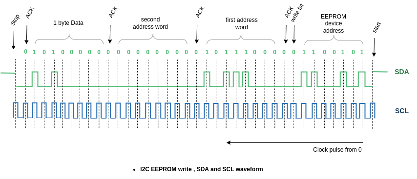
The address frame which is mentioned in the message format is to identify an I2C device. The I2C device sends an ACK bit if the address matches. As we are using a 64kb EEPROM, master sends the EEPROM address and gets ACK. But how can a master access a particular location in the target device? This is possible by using the data frames. Master uses Data frames to send the target address location at which it wants to access i.e either read or write. It requires 13 bits to represent the address locations of a 64kb EEPROM, so master uses two data frames to point an address in EEPROM. The frame format is shown in the image below:

I2C EEPROM write
If the master intends to write the count of blue balls to location 0x1D00, it first sends an address frame specifying the target I2C slave(EEPROM), followed by the write bit.
Upon receiving acknowledgement (ack) from the slave, the master sends the Memory location 0x1D00, with the first and second address words being 0x1D and 0x00, respectively.
The master expects acknowledgments for each address word from the slave, confirming successful address transmission.
Following the acknowledgments, the master proceeds to write the count of blue balls, represented by an 8-bit value (e.g., 0x05), to the slave.
The slave responds with an acknowledgment, confirming the successful reception of the data.
Upon completion of the transmission, the master concludes the communication by issuing a stop condition.
EEPROM device address: 0xA6
Memory location: 0x1D00
write data: 5 (number of blue balls)

I2C EEPROM read
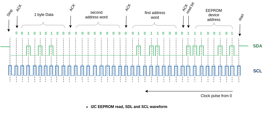
If the master intends to read the count of red balls to location 0x1A00, it first sends an address frame specifying the target I2C slave(EEPROM), followed by the write bit.
Upon receiving acknowledgement (ack) from the slave, the master sends the Memory location 0x1A00, with the first and second address words being 0x1A and 0x00, respectively.
The master expects acknowledgments for each address word from the slave, confirming successful address transmission.
Following the acknowledgments, the master proceeds to red the count of red balls as the Data is transmitted by slave.
The Master responds with an acknowledgment, confirming the successful reception of the data.
Upon completion of the transmission, the master concludes the communication by issuing a stop condition.
EEPROM device address: 0xA6
Memory address location: 0x1A00
read data: 42 (number of red balls).

While the i2c communication protocol is commonly used for various devices, including EEPROMs, the specific addresses and values mentioned in the example are provided for illustrative purposes. In practice, to accurately determine the correct address values and data formats for a particular device, it is essential to refer to the device’s official documentation or manual. Device manuals provide precise information about the i2c communication parameters, ensuring accurate and reliable communication between the master and the specific i2c device.
